Propagation Measurement
Propagation measurements have been made to characterize the UWB signal propagation channel. Using short pulse with sub-nanosecond width, the impulse response of the channel can be observed. Fig.1 is the block diagram of the experimental setup.
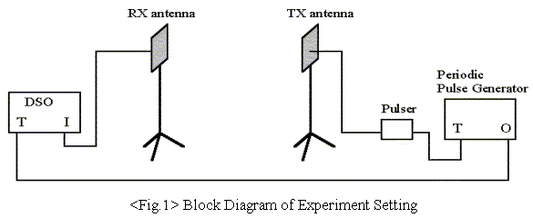
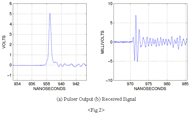
Transmitter consists of a pulser, a periodic pulse generator, and a transmitting antenna. The periodic pulse generator generates a regular frame clock signal with period of 1 microsecond, which triggers the pulser. The periodic pulse generator is also connected to a DSO (Digitized Sampling Scope) by coaxial cable to provide a trigger signal for a measurement of the receiving antenna output. The pulser generates Gaussian-shaped pulses with sub-nanosecond duration. Fig.2-(a) shows the output signal of a typical pulser. Since the antenna system differentiates and filters the pulser’s output, a more complex waveform is detected by the DSO. Incoming signal is differentiated at receiving antenna and observed at DSO. The DSO takes samples over many periods of the transmission to construct one received waveform, and averages several such waveform measurements. Fig.2-(b) shows a typical signal measured by the DSO in an indoor setting. Sixty-four waveforms were averaged in this particular measurement. The LOS (Line Of Sight) path component of the signal is shown in the first two or three nanoseconds of the response, and is followed by a number of multipath components.

 Experiments
 Interference Effects