UWB Interference Effects on an amateur Radio Reciever
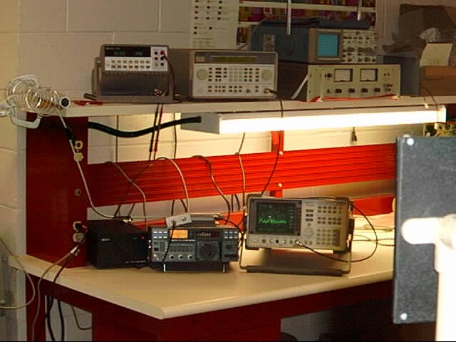
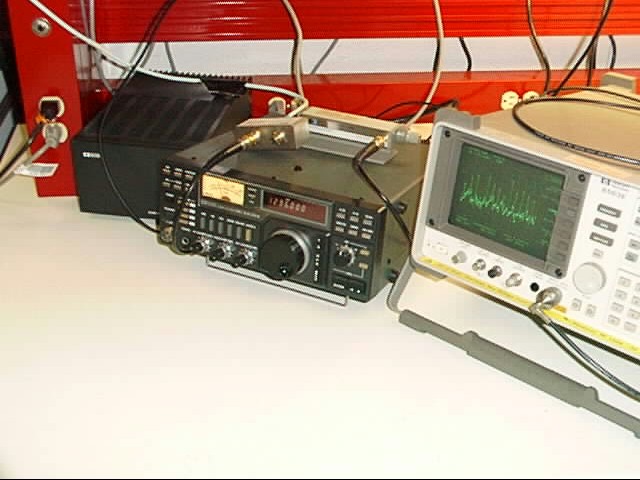
"Using equipment loaned to the UltRa Lab by the American Radio Relay League (ARRL), tests were performed to determine the potential degradation radio amateurs might suffer in the presence of UWB signals. The initial experimental objective was to measure the effect on the Minimum Discernable Signal (MDS), however, after initial testing, it was decided that a more detailed investigation was required.
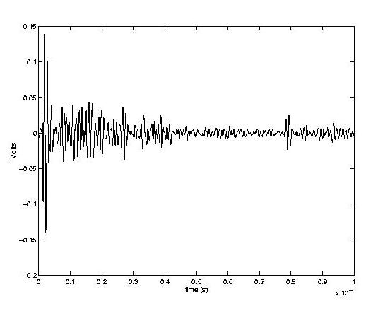
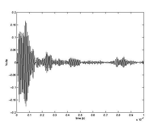
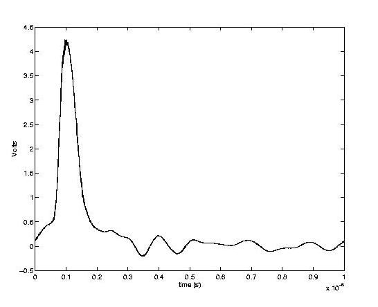
"The three figures below show the UWB waveform at different times. Figure 1 is the transmitted Gaussian pulse, Figure 2 is the pulse as received by a wideband diamond-dipole, Figure 3 is the pulse as received by the loop-Yagi antenna provided by the ARRL. Obviously, the narrower bandwidth of the loop-Yagi antenna permits less total power and spreads the signal in time more than the wideband antenna.
"
"
"
"
"
"
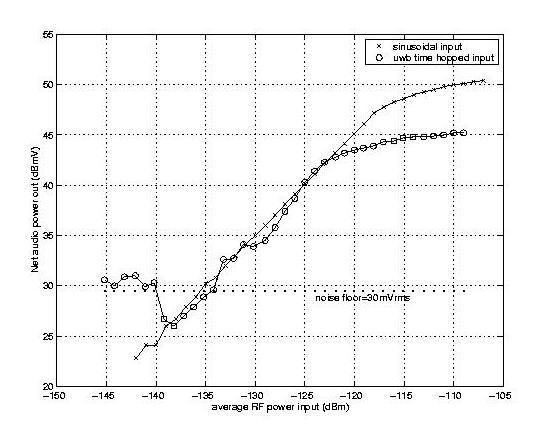
"The first important result comes from the comparison between the linearity of the receiver when excited by continuous wave and impulse like UWB waveforms. The receiver compression point occurs for a lower average input power for an UWB signal than for a CW signal, also resulting in a lower saturated output power, as shown in Figure 4. This is due to the low duty cycle, or equivalently the high peak-to-average power ratio, of the UWB signal, where the compression point is determined by the peak input power but the narrowband output is determined by the average input power.
"
"
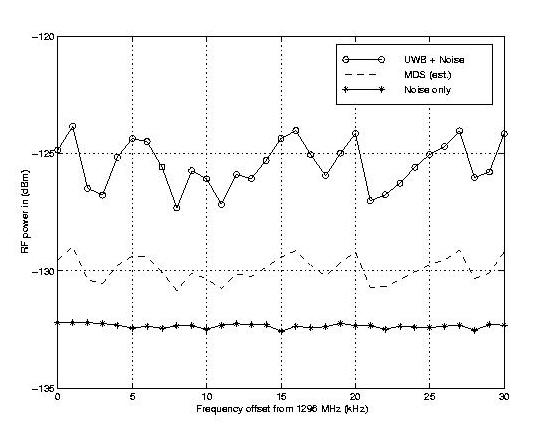
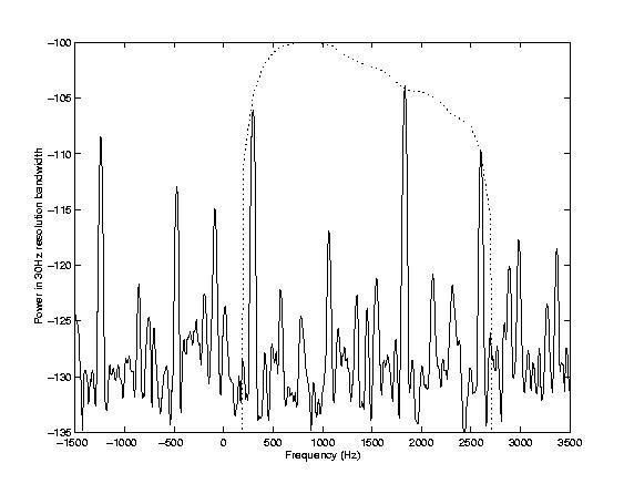
"The second main result is the effect of our UWB signal on the receiver's Minimum Discernable Signal. MDS is defined as the input power required to cause a 3dB increase in output power. A clue to how an intefering signal will affect the MDS is the magnitude of it's spectrum over the passband of the receiver; the spectrum of our signal and the receiver passband are shown in Figure 5. The UWB signal exhibits spectral lines at multiples of the code PRF, as demonstrated four of these lines fall within the receiver passband, but the number may change if the receiver is tuned to a different center frequency. From an interference perspective it is desirable to make the UWB spectrum as flat as possible, i.e., closely spaced, small magnitude spectral lines, so that the signal approximates white noise in the victim receiver. In Figure 6 the MDS of the ARRL receiver is shown for noise only, noise plus the UltRa Lab UWB signal, and the predicted MDS for noise plus an UWB signal meeting FCC regulations.
"Here, is also a
spreadsheet with various charts showing the spectrum of hopped and unhopped UWB pulse.The two best charts are probably the first two where the hopped and unhopped spectrums are overlayed over a wide and a narrow bandwidth for comparison.

 Experiments
 Interference Effects