Time Domain Corporation Indoor Channel Database
In 1995 Moe Win, a graduate student at the UltRa Lab, made this collection of measurements with the support of the Time Domain Corporation and the use of their equipment. These measurements were the experimental basis for many of the analyses later published by UltRa Lab researchers. The measurements do not contain a recording of the transmit antenna's excitation or anechoic chamber measurements of a received waveform under ideal propagation conditions. Cable reflections, etc., were considered part of the channel in related papers and experiments (e.g., see the Wave Display and UWB Receiver Performance on the
Experiments page).
Environment
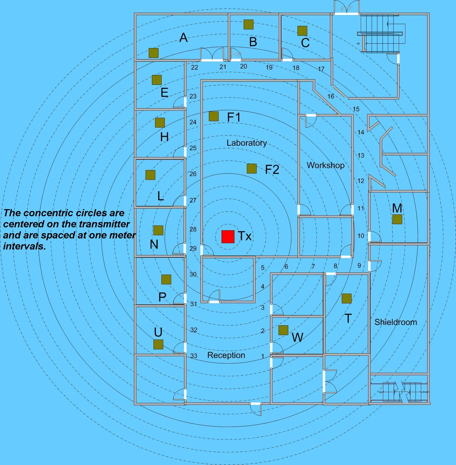
The measurements were made in a modern laboratory/office building with a signal bandwidth of 1.3 GHz. The floor plan of the building is shown in a figure below. Walls around offices are framed with metal studs and covered with plaster board. The wall around the laboratory is made from accoustically silenced heavy cement block. There are steel core support pillars throughout the building, notably along the outside wall and two in the laboratory itself. The shield room's walls and door are metallic. The transmitter is kept stationary in the central location of the building in a laboratory denoted by F. The transmit antenna is located 165 cm from the floor and 105 cm from the ceiling.
Measurements
The best estimate of the received waveform under free-space propagation conditions for the equipment used in these measurements is contained in the file CLEANWAVE
(click here to know more). This measurement was made with one meter separation between transmit and receive antennas. Hence the first few nanoseconds of the obvious response function are nearly multipath-free. This portion of the measured pulse response has been used as a template design for correlation receivers, as a reference for radiated power levels, etc.
Multipath profiles are measured at various locations in 14 different rooms and along the hallways. In each room, 300 ns long response measurements are made at 49 different locations arranged spatially in a level 7 * 7 square grid with 6 inch spacing between measurement points in a one square yard. Each location on the grid is numbered as (i,j) where i represents the row index and j represents the column index of the grid. As a convention, the first row is always parallel and adjacent to the north wall of the room. The receiving antenna is located 120 cm from the floor and 150 cm from the ceiling. This antenna height is envisioned to be typical for future indoor applications. A single multipath profile of 1000 ns duration, which captures the response of two successive probing pulses, is also made in each room. This is to verify that multipath profiles of the first probing pulse have decayed before the response to the next pulse arrives at the receiving antenna.
The measurement equipment contained some cable reflections, and the effect of these has not been removed from the data.
There are primarily two types of Data, which can be obtained from following links:
Note: The last 2 digits in the file names correspond to the matrix indices(i,j) of the square grid. Data with 1000 ns duration is kept in files with suffix as 99. A 'jpeg' file is also associatated with every room depicting the room.

 UWB Database
 MIMO database